Get a quote
Complete a few details about your project/needs and we will provide an indicative cost.
Provide more information, and we will issue a formal quotation.
Here are some frequently asked questions about air tightness testing and sound insulation testing.
Download our testing checklist PDFs
All new buildings of all types need to be tested to evidence energy efficiency. It is possible to avoid testing individual houses and small commercial buildings however, it is not advisable. This is because the air permeability value in energy performance calculations will be estimated and likely poor. This makes it difficult and/or expensive to achieve the overall Energy Performance of the building.
On larger residential developments, it may be possible to test a sample of units rather than every single one but, this only applies to developments started under older versions of Part L. In practice, a large proportion of the units will still need to be tested as relatively small variations in size, position and openings will be considered a different type. In addition, to use tested results on untested plots, you will need to achieve ‘2’ better on the tested units, which is difficult to achieve.
ATTMA is the Air Tightness Testing Measurement Association. It operates the largest and longest-established approved competent persons scheme for air testers. Air testers must be a member of such a scheme and must hold the appropriate level of registration for the project they are undertaking. Level 1 is only for dwellings and small, single-fan buildings other than dwellings. Level 2 is required for the majority of buildings other than dwellings.
The maximum air permeability allowed on any tested unit is ‘8’ (‘10’ for older versions of Part L), however, because of the trade-off of factors to achieve the overall calculated energy performance of the building/unit, it is more typical to need to achieve ‘4-6’.
‘10’ is the equivalent of a 20p piece-sized hole in every square metre of the envelope area. The envelope area is the ‘external’ surface of the unit/building. This covers the total area of the floors, wall and ceiling which border the outside, or a neighbouring unit for flats and attached houses. This is calculated by the air testing company.
Air permeability is expressed in m3/(h.m2)@50Pa, this represents the volume of air being lost, every hour, through unplanned ventilation (gaps, cracks and holes). It covers every square metre of the envelope area when there is a pressure difference of 50Pa between the inside of the building/unit and the outside.
Targets for air permeability tend to be significantly lower than the maximum allowed by Building Regulations and they will only get lower and less flexible as efforts to achieve Net Zero ramp up.
The following provides an indication of what the target numbers mean in terms of areas of concern, construction methods, etc:
The following numbers refer to air permeability in m3/h/m2@50Pa
8-10
5-8
3-5
1-3
Less than 1
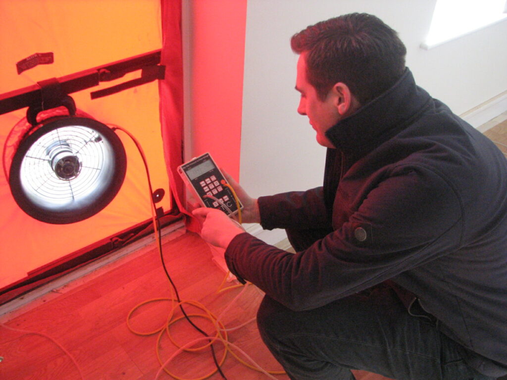
The test is a pressure test with fans used to create a pressure difference between the inside and outside of the building/unit. Knowing how much air is being used to maintain this pressure, provides a comparable measure of the volume of air escaping through gaps, cracks and holes. A negative or positive pressure difference can be created. The fan or fans are typically installed into a door using a ‘blower door fan’ template. The test itself only takes a few minutes but set up and preparation means that testing a typical house or flat takes 15-60 minutes. For larger buildings, it may take 2-6 hours depending on size and complexity. The pressure differences generated are small, so no damage will be done to the building or occupants.
Timing is key, the majority of test failures occur because the building/unit simply isn’t sufficiently complete. However, leaving it to the last minute puts added pressure, especially if there is a problem. We are happy to advise on timings.
If you have several dwelling units of similar design to test, it is preferable to spend time/effort on the first completions (e.g. show home). This will help to establish what jobs need to be finished to get the desired result. This can inform the timing of future tests and the results that should be achieved.
For houses and flats of standard construction, it is possible to achieve reasonable air tightness without having to use specialist products and techniques. It requires close control of trades whose work impacts the air barrier:
Dry liners – to ensure there is a continuous ribbon of plaster at the foot of the boards
Window/door fitters – external doors and windows are sealed around and create a good seal when closed
Plumbers – sealing around pipes and ductwork
Electricians – sealing around cabling
Bathroom and kitchen fitters – ensuring pipe work is sealed where it penetrates the air barrier and/or there is continuity of sealants.
It is also important to have good attention to detail in the final finish e.g. mastic sealing, to ensure continuity is achieved, especially in bathrooms and kitchens. This means the unit must be nearly ready for occupation before being tested, which creates an issue if the building/unit fails.
When targeting a high level of air tightness (4 and under as a guide) then specialist membranes and tapes should be used to create a continuous air barrier within the construction detailing. This means that you are not relying on decorative finishes and mastic seals.
For unusual constructions or commercial buildings, the air barrier tends to need much more careful consideration and design. This is because of the complexities of achieving continuity between the walls and the roof, as there are more ‘hidden’ areas (suspended ceilings and raised floors) and a greater number/scale of service penetrations (air-con, IT and fire sealing). It is important to have an appreciation of the air barrier and what jobs need to be completed when planning the air test.
The easiest and most common way to identify air leakage paths is to feel them during or after the test. By depressurising the building/unit (drawing air out using the fan), the air paths should be identifiable as draughts. Where it isn’t easy to feel or pinpoint the draughts, smoke can be used to make the leakage paths visible.
In many cases, it can be relatively easy to quickly address the issue permanently and repeat the test. Where the failure is more significant, or difficult to access, a further visit may need to be scheduled. If the result is close to achieving the target or design air permeability, it is worth checking with your energy assessor as to whether the performance is good enough to achieve the overall energy targets.

Approved Document E requires evidence of sound insulation performance of party walls and floors for:
These could be newly built or created through a material change of use, for example, a shop or office converted into flats.
There are 2 routes to compliance:
There are pros and cons to each approach, so select the route that is best suited to you. Robust Details mean that little to no site testing will be required, but not every eventuality can be covered by them. They are designed to comfortably exceed the requirements to allow some leeway for variation in site installation. This can mean they are more expensive to construct than what is necessary to meet the requirements when tested on-site.
The arrangement of rooms along party walls may mean that it is not practicable to undertake sound testing. The requirements relate to party walls between ‘habitable’ spaces – these are rooms used for living, sleeping and eating, not bathrooms, toilets, circulation spaces or corridors.
Approved Document E includes a sampling regime for houses, flats and rooms for residential purposes. The samples are based on a ‘set of tests’ for every 1 in 10 units:
For houses, a set is 2 airborne sound insulation tests on party walls – so for every 10 units, 2 tests would be required (this also means 2 tests would be required for 2 units)
For flats, a set is made up of 6 tests:
So for every 10 units, 6 tests would be required, depending upon the layout of the flats it may not be possible to complete all 6 tests on smaller developments. An example is if the flats are separated by a stairwell, so there are no party walls between the flats.
If the flats are above/adjacent to commercial spaces such as shops, additional testing is required between the commercial areas and flats to confirm that the airborne sound insulation is sufficient.
For rooms for residential purposes, a set is made up of 3 tests:
So, for every 10 units, 3 tests would be required.
The requirements are as follows:
| Airborne Sound Insulation | Impact Sound Insulation |
Newbuild houses | > 45 dB | N/A |
Newbuild flats | > 45 dB | < 62 dB |
Newbuild rooms for residential purposes | > 43 dB | < 62 dB |
|
|
|
Converted houses | > 43 dB | N/A |
Converted flats | > 43 dB | < 64 dB |
Converted rooms for residential purposes | > 43 dB | < 64 dB |
Sound is measured in decibels (dB). A whisper is about 30 dB, normal conversation is about 60 dB.
The targets are based on setting a ‘reasonable’ level of sound insulation. For a normal conversation in a neighbouring property, sound insulation of 45 dB or more would reduce this to an imperceptible level. If the neighbours were watching a film at 80 dB, the noise is likely to be audible but drowned out (masked) by day-to-day noises in a property.
The regulatory levels do not mean the wall or floor is soundproof. If the neighbours are having a loud party and you are trying to sleep then it will be disruptive, even if the wall/floor passed the test.
Decibels are on a logarithmic scale which means that a 6 dB difference in sound pressure level is equivalent to a halving/doubling of the sound energy. This means that being 6 dB or more under or over the requirements represents a significant failure.
The airborne test is based on making a loud noise (around 100 dB) using a loudspeaker emitting pink noise (a bit like TV static) on one side of the wall/floor. The sound level in the source room (where the loudspeaker is placed) is measured. With the loudspeaker in the same position at the same level, the sound level is measured in an adjacent room (the receive room) on the other side of the party wall/floor. Measurements are taken in different positions in both rooms and averaged to get an accurate picture of the sound fields. The difference (D) between sound pressure levels in the source and receive rooms is the reported sound insulation in decibels. This needs to be ABOVE the required level in Part E.
The impact test is based on a ‘tapping machine’ which drops small weights onto the uncovered floor to represent footfall and stimulate structure-borne noise. In this case, the sound is only measured in the room below (the receive room). Again, multiple positions and readings are taken and averaged. The sound insulation level (L) in decibels needs to be BELOW the required level in Part E.
Measurements are taken for reverberation (echo) and background which are factored into the calculation. Readings are weighted to reflect the human hearing range and perception of loudness. In addition, the airborne result includes corrections (Ctr) to reflect sensitivities to lower frequency noise.
Unfortunately, sound insulation issues are unlikely to be a quick fix. The sound insulation properties of a wall or floor are based on a combination of the combined mass, stiffness, damping and critical/coincidence frequencies of the products/materials that make up the floor and wall. Sound insulation is affected by their relative arrangement, along with voids, insulation and isolation from each other and the surrounding structure.
In instances of a specific problem, the test engineer may be able to hear (using their ear and the sound level meter) whether the noise transmission is greater in a part of the room. This may relate to an obvious feature e.g. a structural beam or column.
Sometimes, it is clear that noise levels are greater close to the wall than in the middle of the room. This suggests that sound is flanking around the floor via the walls. If the noise is evenly spread it suggests there is an issue with the makeup of the floor or wall. The frequency of the noise can indicate whether the problem is linked to a lack of mass or another cause.
Based on observations on site and the shape and levels of the graph in the report, it is often possible for an acoustic consultant to determine the issue and suggest remedial solutions. Where the problem is less evident, a separate visit to the site for further investigation may be required before proposing solutions.
Typically, solutions are invasive and expensive and could mean adding ‘sacrificial’ walls or ceilings, which eat into valuable space. In some cases, it is necessary to remove existing walls and floors to replace the materials or reconfigure the arrangement. For this reason, we strongly advise that you consult your architect or an acoustic consultant to review the proposed wall/floor details against the suggested solutions in Approved Document E before starting work. This will minimise the chances of issues during sound testing.
Complete a few details about your project/needs and we will provide an indicative cost.
Provide more information, and we will issue a formal quotation.
Air Leakage Testing provides accredited Air, Acoustic & Ventilation testing services.
Company Registration No. 04368485
VAT No. 795 7122 93
© Air Leakage Testing Limited
Contact Details
Email: info@airleakagetesting.co.uk
Tel: 01799 540220
Address:
7 Lawson Way, Aylesbury
Buckinghamshire
HP18 0UW